Trending

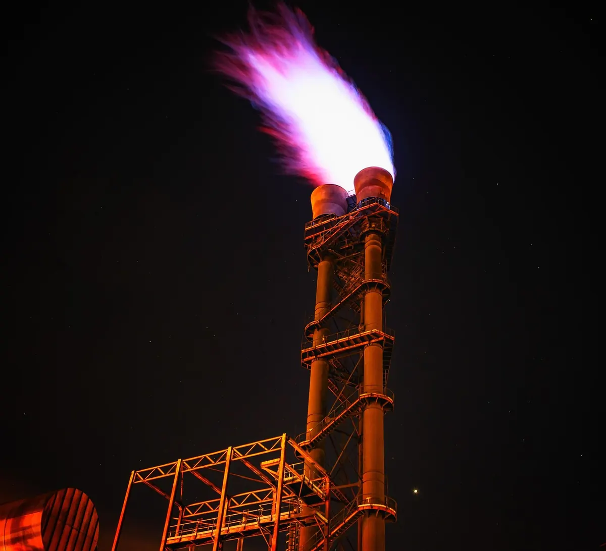
A flare stack is defined by two numbers: the relief load it has to burn and the height that keeps the radiation it produces at a level people and equipment can tolerate. Tip type, diameter, materials and structural design all follow from those two. Get them wrong and the cost runs both ways — an undersized stack carries risk into every plant upset, an oversized one wastes steel, plot space and money.
Flare sizing starts with a scenario study, not a spreadsheet.
List every credible relieving case that feeds the header: blocked outlet, loss of cooling water, loss of power, control valve failure, external fire, tube rupture, thermal expansion and planned depressurisation. Size each one using a recognised relief methodology, then be honest about which can occur together. On a complex unit, a single contingency is rarely the governing case — a power failure that takes out several systems at once usually is. Avoid both traps: don't stack up failures that cannot realistically coincide, and don't assume relief valves will never lift together when the process clearly allows it.
What you need out of this step:
That last point matters. A blowdown from a high-pressure separator often starts with a fast, light gas release and gets heavier as the inventory drains. Size only the first minute and you may miss the case that produces the largest flame. Equally, a depressurisation that looks modest in mass terms can dominate the dispersion case because it lasts for an hour rather than a minute.
Composition decides almost everything downstream. Molecular weight sets the volumetric flow at the tip and the sonic velocity of the gas. Lower heating value sets the total heat released. Heavier hydrocarbons, and anything with a meaningful aromatic content, smoke — which pushes you towards a steam-assisted or air-assisted tip.
Convert mass flow to actual volumetric flow at tip conditions early; that is the figure tip vendors and structural engineers want. Hydrogen-rich streams deserve a second look: they burn cleanly, but the volumetric flow can be startling for a modest mass flow. And do not forget the toxic side — a stream carrying hydrogen sulphide can satisfy every radiation criterion and still fail on ground-level concentration downwind. Radiation and dispersion are separate checks, and both must pass.
This is usually the constraint that decides how tall the stack has to be. Common industry practice uses three reference levels:
Confirm the figures against your project specification and local requirements before locking them into a calculation. The method itself is straightforward: multiply mass flow by lower heating value to get total heat release, apply a fraction-of-heat-radiated factor for the flame, and treat the flame as a source at its centre. Intensity falls with the square of the distance from that source, so the calculation becomes a hunt for the height that pushes the nearest target outside the limit.
Two details deserve care. The fraction of heat radiated typically sits in the region of 0.2 to 0.3 for hydrocarbon gases, with heavier, smokier streams towards the upper end. And wind matters more than most people assume: a fully bent-over flame is not the worst case. A light wind that tilts the flame towards a nearby structure can give higher radiation at grade than a strong wind that lays it flat. Check a range of wind speeds, not just the design maximum.
With volumetric flow in hand, tip diameter comes from the exit velocity you are prepared to accept. Too fast and the flame lifts off, burns noisily or becomes unstable; too slow and the flame sits tight against the tip, cooking the metal and shortening its life. Typical practice caps continuous flow around 0.2 Mach and emergency relief at roughly 0.5 Mach, but the governing figure belongs in your project specification — check it, along with the vendor's acoustic and smokeless performance data.
Smokeless capacity is a separate rating from maximum flow. A tip might burn 100% of the design load black and smoky while staying clean at only a quarter of it, which is why the smokeless percentage is stated explicitly by the vendor. For a plant where visible smoke carries a penalty, size the tip on the required smokeless rate and let the maximum case ride above it.
Illustrative example. Take a governing case of 4.5 kg/s of 20 kg/kmol gas with an LHV of about 45 MJ/kg. Expanding to near-atmospheric at the tip gives roughly 5.6 m³/s. At 0.5 Mach, that calls for a tip of about 200 mm bore. Total heat release is about 200 MW; at a radiated fraction of 0.22, the 4.7 kW/m² contour falls about 28 m from the flame centre. A stack in the region of 30 m, plus margin for the tallest receptor and flame tilt, is the starting point — not the answer until the structural and dispersion checks are done.
Once the radiation calculation gives you a height, the rest of the system has to survive it:
A flare sizing calculation is finished when the relief load is documented, the composition and its variation over time are agreed, the radiation contours pass at every receptor for a range of wind speeds, and the header hydraulics do not exceed relief valve back-pressure limits. Only then does the height and diameter combination become a purchase order. Review it with the process, safety and structural disciplines together — the number that satisfies one of them frequently surprises the other two.
Photo: Tama66 / Pixabay