Trending

A flare system is the last line of defence on any hydrocarbon plant. When a relief valve lifts, a compressor trips or a unit is depressurised in a hurry, the gas has to go somewhere it can burn safely, well away from people and equipment. The flame at the top of the stack is the visible part, but it sits at the end of a chain of vessels, pipework, seals and instruments that all have to work together. Miss one link and you risk liquid carryover, flashback, or a tip that will not light when you need it most.
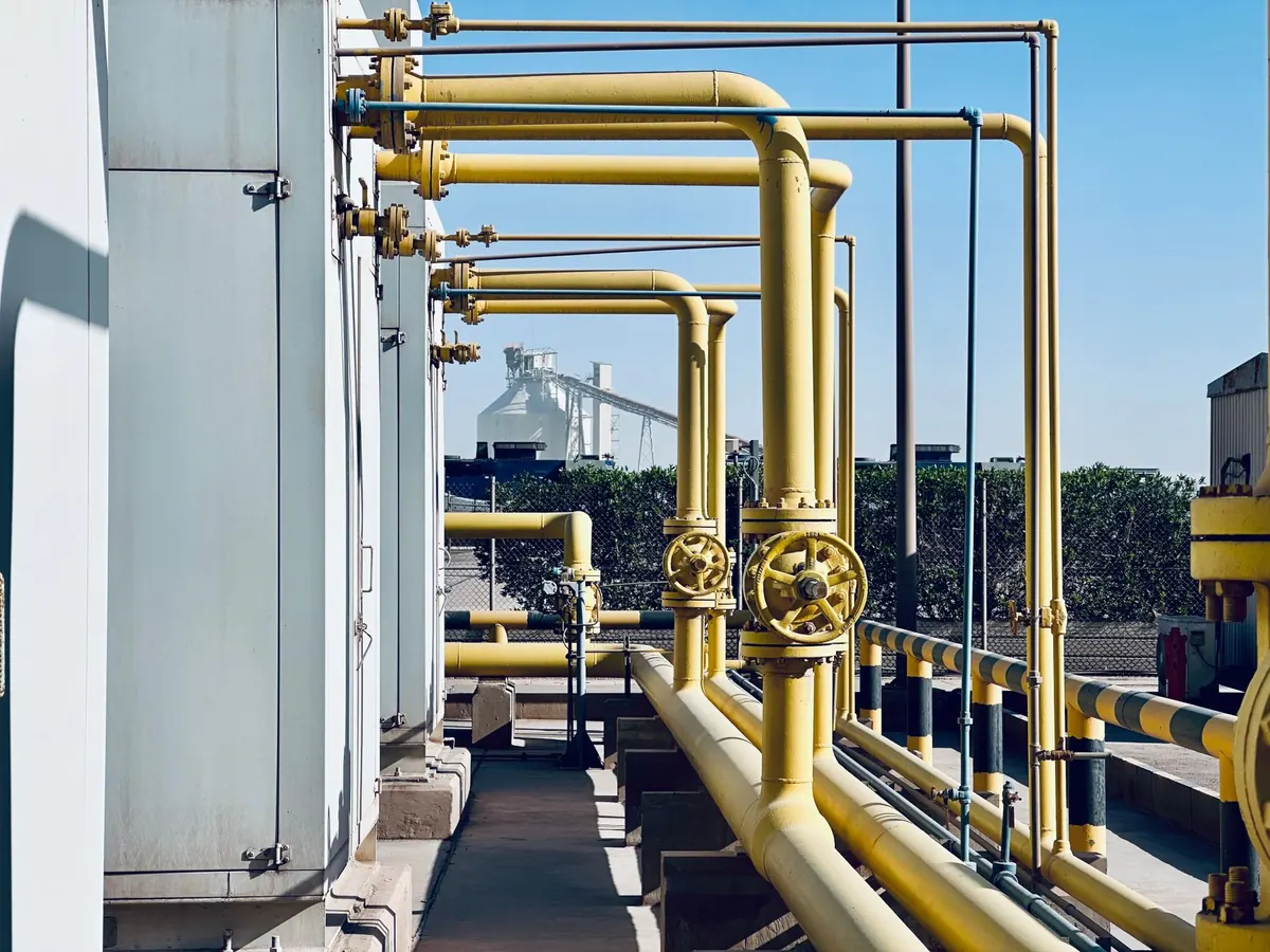
Gas leaving a protected system rarely travels straight to the stack. It passes through a sequence of components, each with a specific job:
The header is usually sloped back towards the knock-out drum, with no low points or open drains that could collect liquid. Pressure drop matters too: a header that is too small pushes up the back pressure on every relief valve connected to it, which can change how those valves perform. That is why flare headers are sized generously and why design codes such as API 521 and API 537 spend so much time on the topic.
Any liquid that reaches a flare tip becomes a burning shower of hydrocarbons. It damages the tip, lands on equipment and can travel well beyond the plant boundary. The knock-out drum exists to prevent that.
Gas enters the drum and slows down, allowing larger droplets to fall out by gravity. Smaller droplets need help, which is where internals come in. A typical horizontal drum has an inlet diverter or distributor to spread the flow, a mesh pad or vane pack to capture fine mist, and a boot at the bottom for water and hydrocarbon draw-off. Some designs use a vertical drum for smaller duties, or a cyclone for high liquid loads.
When a flare stops burning, the gas inside the stack cools and contracts, and wind across the top can pull air downwards. If that air reaches a flammable mixture inside the stack, a flame can travel back down the system. That is flashback, and it is the reason seals exist.
A liquid seal drum forces the gas to bubble through a water layer, which acts as a one-way barrier. A molecular or velocity seal near the stack base uses a change in flow area and direction to make it much harder for air to descend, while a purge gas — a small, continuous flow of fuel gas or nitrogen — keeps a steady upward movement in the stack at all times. Purge rates are set so the mixture in the stack stays outside the flammable range, and purge reduction seals are often fitted to cut the continuous gas consumption.
Rule of thumb: if you can smell gas at the base of the stack or the purge meter reads zero, treat it as a fault, not a nuisance.
The stack height is set mainly by thermal radiation. Gas burns with a flame of a certain length, and the aim is to keep the heat received at grade, on walkways and on nearby structures within acceptable limits. Wind can tilt the flame, so the worst case is usually a strong crosswind, not a still day.
The tip is where the engineering gets interesting. Steam-assisted tips inject high-pressure steam through spokes near the outlet; the steam mixes air into the gas and suppresses smoke. Air-assisted and pressure-assisted tips do the same job with blowers or high-velocity gas. Multi-point and staged tips split the flow across several burners, which helps both smokeless performance and turndown.
Steam control is a balance. Too little steam and the flare smokes; too much and the flame lifts off the tip, roars, and becomes unstable. Operators typically tune the steam-to-gas ratio on a stable flaring rate and then check it again whenever the flow changes significantly. Tip materials also matter — high-temperature alloys, thermal growth allowance, and a tip that is accessible for inspection without shutting the whole plant down.
A flare that is not lit is a release of raw hydrocarbon to atmosphere. Pilots are small, protected flames that stay alight continuously and ignite the main gas when it arrives. Most stacks carry several pilots so that a single failure does not leave the flare unlit, and pilot gas pressure is normally monitored and alarmed.
Ignition is usually provided by a flame front generator or an electronic igniter, operated from a safe location or automatically on high flare flow. Flame detection uses thermocouples, ultraviolet or infrared detectors, or a combination, often backed up by CCTV. Test the ignition panel and prove the detectors on a routine schedule — an ignition system that has never been tried is only an assumption.
Beyond the headline equipment, a flare system relies on flow measurement on the header, steam flow control, radiation monitors, knock-out drum level transmitters, and structural items such as the derrick, guy wires and access platforms. Guy wire tension, corrosion under insulation and the condition of the stack coating are easy to ignore until a wind loading assessment or inspection finds a problem.
Most flare incidents trace back to something simple: a level transmitter that stuck, a pilot that had been out for days, a purge line valved off after maintenance. A short, regular routine catches nearly all of it.
Understand the whole chain and the flame stops being a mystery. It becomes what it should be: a controlled, predictable last line of defence.
Photo: Mumtaz Niazi / Pexels